Step 3. Calibrate the E5080A/B ENA
This topic describes how to use the Keysight E5080A ENA Vector Network Analyzer to calibrate the appropriate PD1000A test fixture. Physical calibration standards are supplied with the test fixture.
Step 1. S-Parameter Hardware Measurement Control
Step 2. Configure S-Parameter Test Settings
If you are using the Keysight E5061B ENA, see Using a Keysight E5061B ENA Vector Network Analyzer
When Should I Calibrate?
-
You must calibrate before first use of the system.
-
You must also recalibrate before testing if you change any of the S-parameter configuration settings (frequency, power, filter bandwidth, sweep mode, etc.).
-
Keysight recommends that you recalibrate the test fixtures periodically, even if you use the same configuration settings and the same kind of DUT for all tests. This is because the TO-220 and TO-247 test fixture contacts may degrade slightly over time, especially with frequent use.
Required Equipment
-
PD1000A control software (to check calibration patterns).
-
E5080A ENA Network Analyzer used with your PD1000A Power Device Advanced Modeling System.
-
PD1000A Bias T Networks (quantity 2 required).
-
Type ‘N’ Male to SMA Female Adapters (Keysight PN 1250-1250, quantity 2 required).
-
SMA cables (Keysight PN: 5062-6682, 7-inch cable, quantity 2 required).
-
Torque wrench (Keysight 8710-1765, 0.90N-m (8 lb-in) 5/16-inch break-over torque wrench) to properly tighten SMA connectors.
-
Mechanical calibration standards (shown in the graphics below). These calibration standards are provided with your test fixture.
-
Test fixture to be calibrated: TO-220, TO-247, or Surface Mount Device (SMD) test fixture.
-
Two calibration kit files are used for the three test fixtures: Fixture_In.xkt for the input port and the Fixture_Out.xkt for the output port. See Install PD1000A Configuration Files for more information.
The TO-220 and TO-247 Calibration Standard Kits have four devices labeled OPEN, SHORT, LOAD, and THRU.
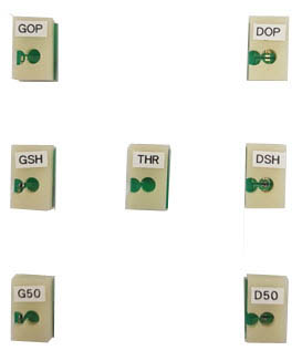
The SMD Calibration Standard Kit has seven devices:
- Input Port Open (labeled OPEN)
- Short (labeled SHORT)
- 50Ω (labeled LOAD) termination
- Output Port Open (labeled OPEN)
- Short (labeled SHORT)
- 50Ω (labeled LOAD) termination
- Through (THROUGH)
Additional or replacement calibration standards are available at: www.keysight.com/find/PD1000A.
Preparation
The PD1000A test fixtures are designed to test semiconductor devices with standard device packaging. Each fixture type has its own calibration standards kit.
Install the Calibration Kit Files
-
Copy the two calibration kit files (Fixture_In.xkt for the input port and the Fixture_Out.xkt for the output port) from: www.keysight.com/find/PD1000A. Copy these two files onto a USB memory stick or directly to the E5080A if it has an Internet connection.
-
Press the CAL button.
-
Touch CAL Sets & Cal Kits > Cal Kit... .
-
Click the Import button.
-
Navigate to where you stored the two calibration kit files.
-
Select the Fixture_In.xkt file.
-
Click Open.
-
Select the network analyzer folder: D:/User > PNACalKits > user.
-
Repeat steps 3 through 6 for the Fixture_Out.xkt file.
-
Click both files, then Save to save them on the network analyzer hard drive.
Set Up the Network Analyzer
-
Connect the text fixture to the E5080A ENA as shown below. Use two PD1000A Bias Tees.
-
Setup the analyzer as follows:
Parameter Value Start Frequency Set the desired Start and Stop frequencies for the frequency range you want to measure. In general, they should be in the range of 10 kHz to 1 GHz (or 3 GHz) Stop Frequency Number of Points 25 Time Domain Mode Low-pass Step Calibration Type 2-port SOLT
Calibration Procedure
Setup for all three test fixtures is the same.
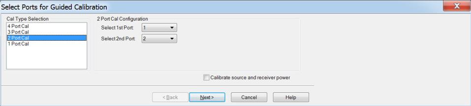
- Once all parameters have been set in the network analyzer, press the analyzer's Cal button. This opens the Select Ports screen.
-
Select 2PortCal. Specify Port 1 as the First Port and Port 2 as the Second Port.
-
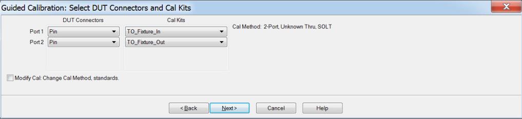
Click Next. This opens the Guided Calibration screen:
-
For Port 1, use the drop-down menu to select:
-
DUT Connectors: PIN
-
Cal Kits: TO_Fixture_In (Fixture_In.xkt)
The same calibration kit files are used for all three test fixtures.
-
-
For Port 2, use the drop-down menu to select :
-
DUT Connectors: PIN
-
Cal Kits: TO_Fixture_Out (Fixture_Out.xkt)
You must insert the calibration standards into the test fixtures for the rest of this procedure. See Inserting Calibration Standards for detailed instructions on inserting the standards.
-
-
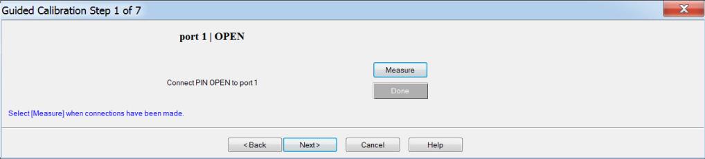
Click Next. This opens the Guided Calibration wizard:
-
Insert the Port 1 OPEN calibration standard into the test fixture between the gate and drain/collector.
-
Click Measure to calibrate for the Open standard.
-
Remove the Port 1 OPEN calibration standard from the test fixture and click Next.
-
Insert the Port 1 SHORT calibration standard into the test fixture between the gate and drain/collector.
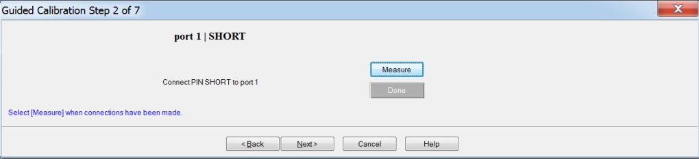
-
Click Measure to calibrate.
-
Remove the Port 1 Short calibration standard from the test fixture and click Next.
-
Insert the Port 1 50 W LOAD calibration standard into the test fixture between the gate and drain/collector.

-
Click Measure to calibrate.
-
Remove the Port 1 Load calibration standard from the test fixture and click Next.
-
Insert the Port 2 OPEN calibration standard into the test fixture. The Port 2 OPEN calibration standard goes between the source/emitter and drain/collector.
For the TO-220 and TO-247 test fixtures, use the same OPEN calibration standard as before, but turn it around to fit into the correct sockets on the test fixture.
-
Click Measure to calibrate.
-
Remove the Port 2 Open calibration standard from the test fixture and click Next.
-
Insert the Port 2 SHORT calibration standard into the test fixture between the source/emitter and drain/collector.
For the TO-220 and TO-247 test fixtures, use the same SHORT calibration standard as before, but turn it around to fit into the correct sockets on the test fixture.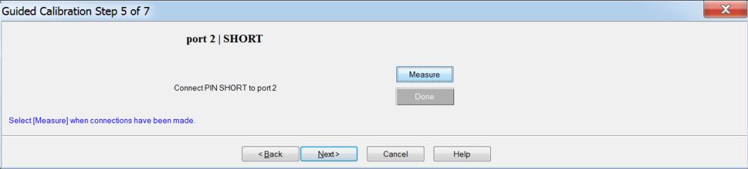
-
Click Measure to calibrate.
-
Remove the Port 2 Short calibration standard from the test fixture and click Next.
-
Insert the Port 2 50 W LOAD calibration standard into the test fixture between the gate and drain/collector.
For the TO-220 and TO-247 test fixtures, use the same LOAD calibration standard as before, but turn it around to fit into the correct sockets on the test fixture.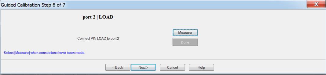
-
Click Measure to calibrate.
-
Remove the Port 2 Load calibration standard from the test fixture and click Next.
-
Insert the THROUGH calibration standard into the test fixture.

-
Click Measure to calibrate. A dialog displays the calculated delay for the THROUGH calibration standard. The calibration is correct if the value is less than 0.2 nS.

-
Ensure that the displayed value is less than 0.2 nS.
-
Click OK to close the dialog and display the final wizard screen.
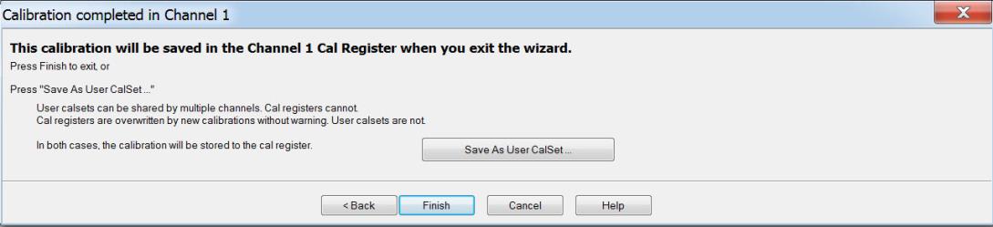
-
Click Save As User CalSet. This saves the calibration information in a form that can be reused and shared by multiple channels.
-
Click Finish to complete the calibration procedure.
-
Remove all calibration standards from the test fixture and replace the DUT.
Next Step:
See Also:
Step 1. S-Parameter Hardware Setup